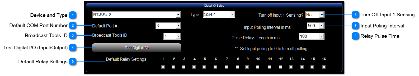
Digital I/O (Input/Output) Setup Area
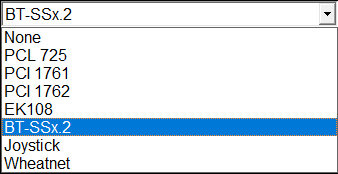
 Device and TypeThe 2 most common devices are a Broadcast Tools Switcher (BT-SSx.2) and WheatNet Interface (Wheatnet).
The other interfaces are only there for backward compatibility and not recommended for use now.
If you are not using an I/O device, select "None".
Here is the complete list:
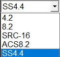
If you select BT-SSx.2 for a Broadcast Tools device, you will also see the Type drop down box where you can select which model you are using.
You will also see the Broadcast Tools ID box appear below and have to choose an ID in the range 0 though 2.
ID 1 is recommended and set by dipswitch on the unit itself.
|
|
 Default COM Port NumberIf you I/O Device is serial (RS-232), put the COM Port number in this box.
The supported range is 1 through 8.
|
|
 Broadcast Tools IDThis box only appears if you have selected BT-SSx.2 for a Broadcast Tools device.
ID 1 is recommended and set by dipswitch on the unit itself.
|
|
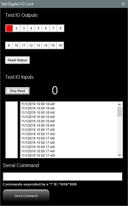
 Test Digital I/O (Input/Output)
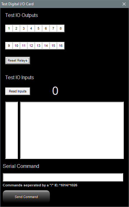
Test Digital I/O brings up the box below and can test communication with the I/O device attached to the COM port.
Test IO Outputs: Click an output relay number and the relay in the device should close (Turn ON) and the relay number lights up red.
Click the Reset Relays Button to open (Turn OFF) all of the relays.
If you click the Read Inputs Button you will see the Polling information in the box like the picture above-middle.
This indicates a good COM port, but no communication to a device.
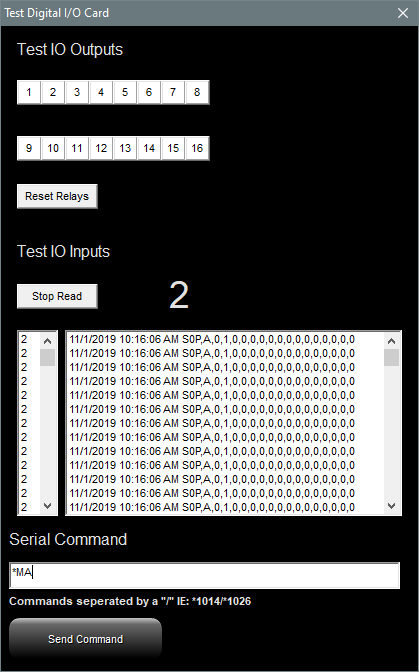
If a serial I/O device is connected and communications are established you would see other information like the picture above-right.
A field of comma separated zeros and a big Zero to the right of the Stop Read Button indicates that no PIP relays are currently being pulsed.
The 1 in the picture above-right and the big 2 to the right of the Stop Read Button indicates that PIP 2 is being closed.
DJB Radio On Air will interpret that as Input 2 being triggered.
Send Command: You can type in a command to send to the I/O Device and click the Send Command Button.
If a serial I/O device is connected and communications are established the switcher will execute the command.
In the above-right picture, the command *1MA will tell Broadcast Tools device ID1 to Mute All.
|
|
 Default Relay SettingsSome of the devices on the list support checking the default relays to be turned on at startup.
|
|
 Turn Off Input 1 SensingThis will disable input 1.
|
|
 Input Poling IntervalThe time in milliseconds between polls. The DJB Radio On Air polls the I/O device to see if any inputs are active.
If you set the polling interval to zero, it disables the polling function thus disabling Inputs.
|
|
 Relay Pulse TimeThe length of time in milliseconds a relay is held closed when it is Pulsed.
Relays can be:
Closed (Turned ON),
Opened (Turned OFF), or
Pulsed (Turned ON for the number of milliseconds in the box and then turned OFF)
|
|